

New Century Electrical
Products
Integrated Automation Device for the Unit
- Overview
- Main Features
- Main Indicators
- Main functions
- Device Configuration
The XSJ-13606 unit comprehensive automation device realizes the collection of auxiliary switch position signals of primary equipment on site, AC analog signals of current and voltage, and DC signals such as temperature, water level, and pressure, and performs logical operations. The collected data and calculated data are uploaded to the touch screen via RS-232 communication, and uploaded to the communication management machine or backend system via Ethernet or RS-485 interface. When the logical operation determines a running fault or normal start-stop operation, the device will issue control commands, and the output signals will control related equipment through an extended relay.
The XSJ-13606 unit comprehensive automation device is suitable for comprehensive control of brushless and brushed generator sets with a rated voltage of 400V (or 660V) and a single machine capacity of 1000kW and below. It is used to complete the measurement, protection, synchronization, temperature and speed control, unit start-stop control, communication functions, and on-off control of the primary circuit.
1) Unit measurement function.
2) Automatic start and stop.
3) Automatic synchronization and grid connection.
4) Automatic power adjustment according to the given load.
5) Automatic start and stop based on water level under single or multiple unit coordination, automatic load distribution according to water level, and operation at high water level.
6) Conventional manual operation and conventional instrument monitoring.
7) Unit protection function.
8) Can connect to a computer to form a network, completing centralized management, centralized control, data recording, querying, printing, etc. It can also connect with the dispatch center to achieve unattended operation and minimal staffing.
9) Supports GPRS Mobile SMS function (optional), allowing quick and convenient reporting of power station operating status, operating parameters, operation records, accident reports, etc. through mobile information. This helps power station management personnel quickly understand the operation status and guide accident handling.
1. Technical Parameters
Serial Number
Parameter Name
Technical Parameters
1
Working Power Supply
DC 24V
2
Input Voltage
DC 24V
3
Rated AC Voltage
380/
 V or 100/V
4
Rated AC Current
5A
5
Rated AC Frequency
50Hz
6
Phase Voltage Normal Measurement Range
2V~400V
7
Current Normal Measurement Range
0.05In~10In
8
Current and Voltage Measurement Accuracy Level
0.5 Level
9
Power Measurement Accuracy Level
1 Level
2. Appearance Size
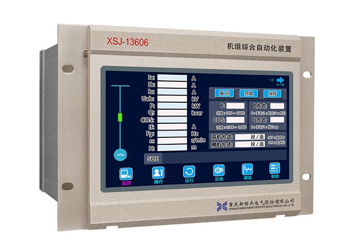
The dimensions of the XSJ-13606 unit comprehensive automation device are 260mm wide × 177.5mm high × 180mm deep.

XSJ-13606 device outline dimensions and front view

XSJ-13606 device rear view
Classification
Project
Configuration Description
Protection
50/51
Overcurrent Protection
■ (Overcurrent I stage forward protection, Overcurrent I stage reverse protection, Overcurrent II stage protection)
51
Overload Protection
■ (Alarm)
51
Negative Sequence Overcurrent Protection
■
59
Overvoltage Protection
■ (Alarm, Action)
27
Undervoltage Protection
■
81
Frequency Protection
■ (Low Frequency, Over Frequency)
40
Loss of Magnetism Protection
■
50T
Non-Electric Quantity Protection
■ (Alarm, Action)
Synchronization
Check System No Voltage Closing
■
Check Synchronization Closing
■
Measurement
Remote Measurement
Three-phase Current, Three-phase Phase Voltage, System Voltage, Excitation Voltage, Active Power, Reactive Power, Power Factor, Generator Frequency, System Frequency, 3rd Harmonic Voltage, etc.
Remote Signal
■
DC Analog Measurement (4-20mA)
4 Channels (1 channel defined as water level signal, cannot be changed; the remaining 3 channels can be defined according to specific engineering projects)
Temperature
Temperature Inspection
9 Channels
Speed
Speed Measurement
■
Control
Circuit Breaker Remote Control Operation
■
Unit Automatic Start and Stop Control
■
Unit Accident Shutdown, Emergency Shutdown Control
■
Manual Active and Reactive Regulation
■
Automatic Regulation According to Given Power
■
Power Generation According to Water Level
Automatic Start Generation with Water
■
Automatic Shutdown for Water Storage without Water
■
Automatic Load Increase with High Water
■
Automatic Load Decrease with Low Water
■
Excitation Operating Mode
Constant Voltage Control
■
Constant Power Factor Control
■
Constant Excitation Current Control
■
Automatic Tracking of Grid Voltage
■
Automatic Transition to Constant Power Factor Control After Grid Connection
■
Fault Diagnosis
Self-Diagnosis
■
Self-Recovery
■
TV Disconnection
■
TA Disconnection
■
TWJ Abnormality
■
Current Phase Sequence Abnormality
■
Voltage Phase Sequence Abnormality
■
Device Power Failure Alarm
■
Communication Abnormality Alarm
■
Event
Event SOE Record
■
Device Power On, Power Off, Reset Record
■
Accident, Manual Recording (requires background display)
■
Debugging
Device Output Drive
■
Event Report Clearance
■
Circuit Breaker Test Position
■
Hardware Configuration
Human-Machine Interface
7 Inch
Input Quantity
Standard 23, Additional Optional 38
Output Quantity
Standard 23, Additional Optional 38
Ethernet Communication Interface
1 Channel (IEC60870-5-103 Protocol)
RS-485 Communication Interface
1 Channel (Standard Modbus Protocol)
Chassis Structure
4U 19"/2
Voltage Transformer Wiring Method
YY
©️ 2025 Chongqing New Century Electrical Co., Ltd. All Rights Reserved.
